Sunday 12 May 2013

The Circuit Diagram of Computer Mouse

In this post I would like to attach Computer Mouse Circuit Diagram...


Optical Mouse Circuit Diagram

Optical Mouse Circuit Diagram

 This circuit diagram will be modified and connected to EOG signal. The development of this computer mouse controlled by EOG is still under construction.

Friday 8 March 2013

Computer Mouse Circuit


In computing, a mouse is a pointing device that functions by detecting two-dimensional motion relative to its supporting surface. Physically, a mouse consists of an object held under one of the user's hands, with one or more buttons.

The mouse sometimes features other elements, such as "wheels", which allow the user to perform various system-dependent operations, or extra buttons or features that can add more control or dimensional input. The mouse's motion typically translates into the motion of a pointer on a display, which allows for fine control of a graphical user interface.


Who Invented Mouse???

Invented by Douglas Engelbart in 1963 while working at Xerox PARC, who at the time was working at the Stanford Research Institute, which was a think tank sponsored by Stanford University. The mouse allows an individual to control a pointer in a graphical user interface (GUI). Utilizing a mouse a user has the ability to perform various functions such as opening a program or file and does not require the user to memorize commands, like those used in a text-based command line environment such as MS-DOS.

The Mouse was originally referred to as an X-Y Position Indicator for a Display System. Xerox later applied the mouse to its revolutionary Alto computer system in 1973. However, because of Alto's unfortunate success, it was first widely used in the Apple Lisa computer. Today, a pointing device is found on virtually every computer.

 
Mechanical Mouse


MECHANICAL MOUSE.


A mechanical mouse is a computer mouse that contains a metal or rubber ball on its under side. When the ball is rolled in any direction, sensors inside the mouse detect this motion and move the on-screen mouse pointer in the same direction.


Optical and Laser Mouse


OPTICAL MOUSE


Optical mice make use of one or more light-emitting diodes (LEDs) and an imaging array of photodiodes to detect movement relative to the underlying surface, rather than internal moving parts as does a mechanical mouse. A laser mouse is an optical mouse that uses coherent (laser) light.

The earliest optical mice detected movement on pre-printed mousepad surfaces, whereas the modern optical mouse works on most opaque surfaces; it is unable to detect movement on specular surfaces like glass. Laser diodes are also used for better resolution and precision. Battery powered, wireless optical mice flash the LED intermittently to save power, and only glow steadily when movement is detected.


Mechanical Vs. Optical Mouse 


Cursor Accuracy 
The cursor accuracy of an optical mouse is typically high as it can analyze changing positions at 700 mm/sec and read up to 200 to 300 dots per inch. This means that it reads its location fast with high precision.
In comparison to a mechanical mouse, an optical mouse does not wear down in accuracy because it does not have the same moving parts that a mechanical mouse has. However, the accuracy can be reduced if the open hole leading to the laser area is dirty.

 
Convenience 
The optical mouse can be used on almost any surface as long as the laser can read the surface it is on. This means you could use the mouse on your leg, a notebook or almost any other object. 
Mechanical mice require a hard, flat and frictional surface for proper functioning. This makes the optimal mouse much more convenient to use on the go. 
 
Energy 
One area that the optical mouse suffers is in energy use.An optical mouse requires a steady stream of energy so that it can constantly relate the mouse's position to the cursor due to the constant images the mouse takes.  Since friction and the movement of a tracking ball are used for a mechanical mouse, the energy required for its use is significantly lower than the optimal mouse. 
 
Surface Issues

The optical mouse uses the different surface images to adjust the cursor on your screen; however, surfaces that are shiny or are made of glass mirror and reflect the laser picture back to the picture reader software. This tricks the software into thinking that the mouse is not moving because its seeing its own reflection. You should avoid these types of surfaces when using an optical mouse.
A mechanical mouse has a ball that turns rollers inside. If friction is lost between the ball and the mousing surface, or between the ball and the rollers, the mouse fails to work. In order to assure good contact with the mousing surface, the ball must be fairly heavy. When you change directions with the mouse, you must make the ball change rolling directions--an action that inertia likes to prevent. 
 
 
Optical mouses generally have less moving parts than mechanical mouses in addition they have much higher sensitivity and are useable on almost any surface. This makes optical mouses much more popular than mechanicals, as a result the use of mechanical mouses is on the decline.  


reference:
wikipedia-mouse(computing)

Tuesday 5 March 2013

ELECTRO_OCULOGRAPH SIGNAL

The electrooculogram (EOG) is the electrical signal produced by the potential difference between the retina and the cornea of the eye. This difference is due to the large presence of electrically active nerves in the retina compared to the front of the eye. Many experiments 
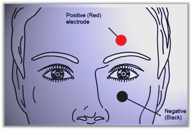
show that the corneal part is a positive pole and the retina part is a negative pole in the eyeball.

Eye movement will respectively generates voltage up to 16uV and 14uV per 1° in horizontal and vertical way. The typical EOG waveforms generated by eye movements

The diagram top figure shows the three types of eye movements and the bottom figure shows the original EOG waveform.


Positive or negative pulses will be generated when the eyes rolling upward or downward. The amplitude of pulse will be increased with the increment of rolling angle, and the width of the positive (negative) pulse is proportional to the duration of the eyeball rolling process.

When the eyes are stationary or when the eyes are looking straight ahead, there is no considerable change in potential and the amplitude of signal obtained is approximately zero. 

When the eyes are made to move upwards, then there results an action potential, which when measured will give a value of -0.06v to +0.06v. Similarly a downward movement of the eyes will give a similar voltage with opposite polarities to that obtained due to the left movement.


reference:

Literature Review of Electrooculography (EOG)

WHAT IS ELECTRO-OCULOGRAPHY (EOG)???


An Electrooculogram or EOG is the resulting signal of the potential difference caused by eye movements. The voltage difference is measured between the cornea and the retina. The resting potential ranges from 0.4mV to 1mV and a pair of electrodes are commonly used to detect this signal, but the voltage difference when there's an eye movement can be as small as just some microvolts. Depending on the eyes' position, an electrode is more positive or negative with respect to the ground electrode. Therefore, the recorded signal is either negative or positive when moving the eyes.


WHO DISCOVERED OEG???

In 1849, Du Bios-Reymond found there was a certain relationship between eye movements and electrode potentials from the skin surface. Medical studies proved that the potential difference, which is commonly called the resting potential, arose from hyperpolarisations and dehyperpolarisations existing between the cornea and the retina. The resting current flows continuously from the retina side to the cornea side, so that an electrical field comes into being with a negative pole at the retina and a positive pole at the cornea. This field changes orientation as the eyeballs rotate. Therefore, a human eyeball can be considered as a spherical battery that the centre of cornea is positive and the retina is negative.


references: